BladeRF output plugin
Introduction
This output sample sink plugin sends its samples to a BladeRF device. It is supported in Linux only.
Build
The plugin will be built only if the BladeRF host library is installed in your system. If you build it from source and install it in a custom location say: /opt/install/libbladeRF you will have to add -DLIBBLADERF_INCLUDE_DIR=/opt/install/libbladeRF/include -DLIBBLADERF_LIBRARIES=/opt/install/libbladeRF/lib/libbladeRF.so to the cmake command line.
The BladeRF Host library is also provided by many Linux distributions and is built in the SDRangel binary releases.
Interface
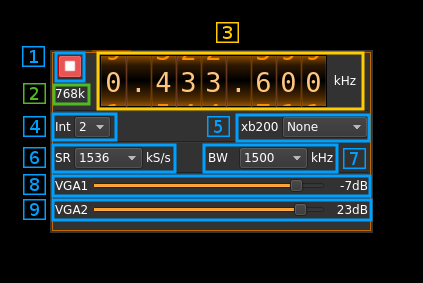
1: Start/Stop
Device start / stop button.
- Blue triangle icon: device is ready and can be started
- Red square icon: device is running and can be stopped
- Magenta (or pink) square icon: an error occured. In the case the device was accidentally disconnected you may click on the icon, plug back in and start again.
2: Baseband sample rate
This is the baseband sample rate in kS/s before interpolation (4) to produce the final stream that is sent to the BladeRF device. Thus this is the device sample rate (6) divided by the interpolation factor (4).
3: Frequency
This is the center frequency of transmission in kHz.
4: Interpolation factor
The baseband stream is interpolated by this value before being sent to the BladeRF device. Possible values are:
- 1: no interpolation
- 2: multiply sample rate by 2
Larger values introduce performance problems.
5: XB-200 add-on control
This controls the optional XB-200 add-on when it is fitted to the BladeRF main board. These controls have no effect if the XB-200 board is absent. Options are:
- None: XB-200 is ignored
- Bypass: XB-200 is passed through
- Auto 1dB: The 50, 144 and 220 MHz filters are switched on automatically according to the frequency of reception when it is within the -1 dB passband of the filters
- Auto 3dB: The 50, 144 and 220 MHz filters are switched on automatically according to the frequency of reception when it is within the -3 dB passband of the filters
- Custom: The signal is routed through a custom filter
- 50M: The signal is routed through the 50 MHz filter
- 144M: The signal is routed through the 144 MHz filter
- 222M: The signal is routed through the 222 MHz filter
6: Device sample rate
This is the BladeRF device DAC sample rate in kS/s. Possible values are: 1536, 1600, 2000, 2304, 2400, 3072, 3200, 4608, 4800, 6144, 7680, 9216, 9600, 10752, 12288, 18432, 19200, 24576, 30720, 36864, 39936 kS/s.
7: Tx filter bandwidth
This is the Tx filter bandwidth in kHz in the LMS6002D device. Possible values are: 1500, 1750, 2500, 2750, 3000, 3840, 5000, 5500, 6000, 7000, 8750, 10000, 12000, 14000, 20000, 28000 kHz.
8: Variable gain amplifier #1 gain
The VGA1 (relative) gain can be adjusted from -35 dB to -4 dB in 1 dB steps. The VGA1 is inside the LMS6002D chip and is placed between the baseband filter and the RF mixer.
9: Variable gain amplifier #2 gain
The VGA2 gain can be adjusted from 0 dB to 25 dB in 1 dB steps. The VGA2 is inside the LMS6002D chip and is placed after the RF mixer. It can be considered as the PA (Power AMplifier). The maximum output power when both VGA1 and VGA2 are at their maximum is about 4 mW (6 dBm).
