11 KiB
DSD (Digital Speech Decoder) demodulator and decoder plugin
Introduction
This plugin uses the DSDcc library that has been rewritten from the original DSD program to decode several digital speech formats. At present it covers the following:
- DMR/MOTOTRBO: European two slot TDMA standard. MOTOTRBO is a popular implementation of this standard.
- D-Star: developed and promoted by Icom for Amateur Radio customers.
The modulation and format is automatically detected and switched.
To enable this plugin at compile time you will need to have DSDcc installed in your system. Please follow instructions in DSDcc readme to build and install DSDcc. If you install it in a custom location say /opt/install/dsdcc you will need to add these defines to the cmake command: -DLIBDSDCC_INCLUDE_DIR=/opt/install/dsdcc/include/dsdcc -DLIBDSDCC_LIBRARIES=/opt/install/dsdcc/lib/libdsdcc.so
DV serial device support
You can use a serial device connected to your system that implements and exposes the packet interface of the AMBE3000 chip. This can be for example a ThumbDV USB dongle. In order to support DV serial devices in your system you will need two things:
- Compile with SerialDV support Please refer to this project Readme.md to compile and install SerialDV. If you install it in a custom location say
/opt/install/serialdvyou will need to add these defines to the cmake command:-DLIBSERIALDV_INCLUDE_DIR=/opt/install/serialdv/include/serialdv -DLIBSERIALDV_LIBRARY=/opt/install/serialdv/lib/libserialdv.so - Enable DV serial devices in your system by checking the option in the Preferences menu. YOu will need to enable the DV serial devices each time you start SDRangel.
Please note that such serial devices work with a serial interface at 400 kb. While this seems large for a serial interface this limits the throughput and hence the capability of decoding several channels in parallel. The software can enqueue requests over many devices so the more you have the more channels you can decode in parallel. Note also that a channel that does not output voice frames will not require a device for decoding so only channels that receive voice frames at any one time will require a DV serial device.
Note also that this is not supported in Windows.
Mbelib support
DSDcc itself can use mbelib to decode AMBE frames. While DSDcc is intended to be patent-free, mbelib that it uses describes functions that may be covered by one or more U.S. patents owned by DVSI Inc. The source code itself should not be infringing as it merely describes possible methods of implementation. Compiling or using mbelib may infringe on patents rights in your jurisdiction and/or require licensing. It is unknown if DVSI will sell licenses for software that uses mbelib.
If you are not comfortable with this just do not install DSDcc and/or mbelib and the plugin will not be compiled and added to SDRangel. For packaged distributions just remove:
- For Linux distributions:
plugins/channel/libdemoddsd.so - For Windows distributions:
dsdcc.dll,mbelib.dll,plugins\channel\demoddsd.dll
For software built fron source if you choose to have mbelib support you will need to have DSDcc compiled with mbelib support. You will also need to have defines for it on the cmake command. If you have mbelib installed in a custom location, say /opt/install/mbelib you will need to add these defines to the cmake command: -DLIBMBE_INCLUDE_DIR=/opt/install/mbelib/include -DLIBMBE_LIBRARY=/opt/install/mbelib/lib/libmbe.so
Interface
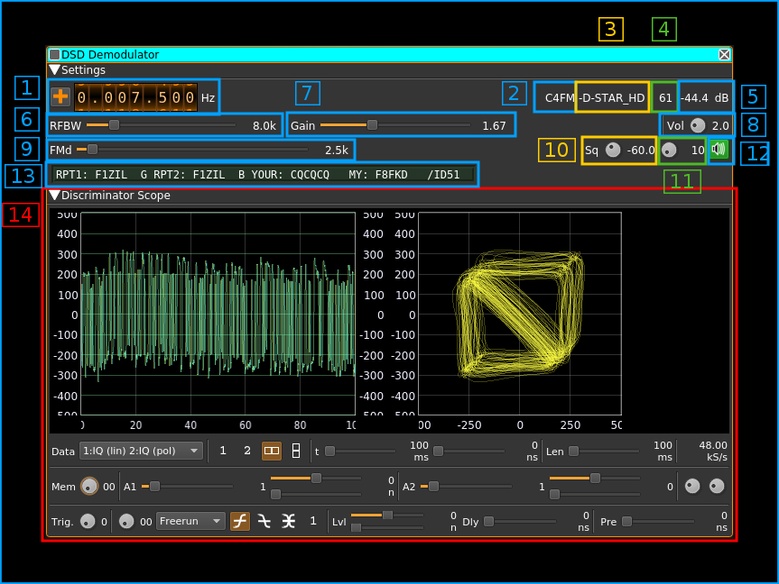
1: Frequency shift from center frequency of reception
Use the wheels to adjust the frequency shift in Hz from the center frequency of reception. Use the "+/-" button on the left side to toggle between positive and negative shift.
2: Modulation detected
This is the type of modulation detected by DSDcc. It can be the following:
C4FM: 4-FSK modulation as implemented for example by Yaesu. It is also the default display. Sometimes 4-GFSK signals can be detected as C4FM if the signal is relatively noisy. This should not affect decoding provided noise is not too strong.GFSK: Gaussian mean frequency shift keying. it is either 2 or 4-FSK (2-GFSK or 4-GFSK). DMR transmissions will typically be identified as GFSK as it is 4-GFSK. D-Star will also be detected as GFSK as it is 2-GFSK.QPSK: At present no decodable transmissions use QPSK.
3: Type of frame detected
This can be one of the following:
+DMRd: non-inverted DMR data frame-DMRd: inverted DMR data frame+DMRv: non-inverted DMR voice frame-DMRv: inverted DMR voice frame(+DMR): non-inverted isolated DMR voice frame(-DMR): inverted isolated DMR voice frame+D-STAR: non-inverted D-Star frame-D-STAR: inverted D-Star frame+D-STAR_HD: non-inverted D-Star header frame encountered-D-STAR_HD: inverted D-Star header frame encountered
4: Decoder input level in %
Most satisfactory decodes for values 50~70%. When no signal is detected it defaults to 91%.
5: Channel power
Total power in dB relative to a +/- 1.0 amplitude signal received in the pass band.
6: Channel bandwidth before discriminator
This is the bandwidth of the pre-discriminator filter
7: Gain after discriminator
This is the gain applied to the output of the discriminator before the decoder
8: Audio volume
This is the audio volume for positive values. A value of zero triggers the auto volume (audio AGC).
9: Maximum expected FM deviation
This is the deviation in kHz leading to maximum (100%) deviation. You should aim for 30 to 50% (+/-300 to +/-500m) deviation on the scope display.
10: Squelch level
The level corresponds to the channel power above which the squelch gate opens.
11: Squelch time gate
Number of milliseconds following squelch gate opening after which the signal is actually fed to the decoder. 0 means no delay i.e. immediate feed.
12: Audio mute and squelch indicator
Audio mute toggle button. This button lights in green when the squelch opens.
13: Format specific status display
When the display is active the background turns from the surrounding gray color to dark green. It shows informatory or status messages that are particular to each format.
13.1: D-Star status display
These is the standard D-Star embedded information that is read from the header frame.
13.1.1: Repeater 1 callsign
13.1.2: Repeater 2 callsign
13.1.3: Destination (your) callsign
13.1.4: Origin (my) callsign
13.2: DMR status display
13.2.1: Station role
BS: base stationMS: mobile stationNA: not applicable or could not be determined
13.2.2: TDMA slot #0 status
slot0: nothing received in slot #0[slot0]: data frame received for slot #0[SLOT0]: voice frame received for slot #0
13.2.3: TDMA slot #1 status
slot1: nothing received in slot #1[slot1]: data frame received for slot #1[SLOT1]: voice frame received for slot #1
13.2.4: Color Code
This is the color code in use (0 to 15). It may briefly change value to a incorrect one. Take into account the value shown most of the time.
14: Discriminator output scope display
The discriminator signal at 48 kS/s is routed to the scope display with the following connections:
- I signal: the discriminator samples
- Q signal: the discriminator samples delayed by the baud rate i.e. one symbol delay:
- 2400 baud: 20 samples
- 4800 baud: 10 samples
- 9600 baud: 5 samples
This allows the visualization of symbol transitions which depend on the type of modulation.
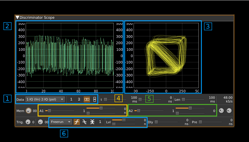
14.1: Setting the display
- On the combo box you should choose IQ (lin) for the primary display and IQ (pol) for secondary display
- On the display buttons you should choose the side by side display
On the same line you can choose any trace length. If it is too short the constellation points will not appear clearly and if it is too long the polar figure will be too dense. Usually 100ms give good results.
14.2: IQ linear display
The yellow trace (I) is the direct trace and the blue trace (Q) is the delayed trace. This can show how symbols differentiate between each other in a sort of eye diagram.
14.3: IQ polar display
This shows the constellation of transition points. You should adjust the frequency shift to center the figure and the maximum deviation and/or discriminator gain to contain the figure within the +/-0.4 square. +/- 0.1 to +/- 0.3 usually give the best results.
2-FSK or 2-GFSK
This concerns the following formats:
- D-Star
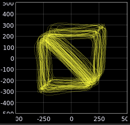
There are 4 possible points corresponding to the 4 possible transitions. x represents the current symbol and y the previous symbol. The 4 points given by their (y,x) coordinates correspond to the following:
- (1, 1): upper right corner. The pointer can stay there or move to (1, -1)
- (1, -1): upper left corner. The pointer can move to (-1, -1) or (-1, 1)
- (-1, 1): lower right corner. The pointer can move to (1, -1) or (1, 1)
- (-1, -1): lower left corner. The pointer can stay there or move to (-1, 1)
As you can see the pointer can make all moves except between (-1, -1) and (1,1) hence all vertices between the 4 points can appear except the one between the lower left corner and the upper right corner.
4-FSK or 4-GFSK
This concerns the following formats:
- DMR
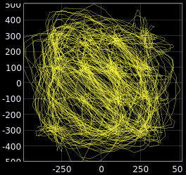
There are 16 possible points corresponding to the 16 possible transitions between the 4 dibits. The 4 dibits are equally spaced at relative positions of -3, -1, 1, 3 hence the 16 points are also equally spaced between each other on the IQ or (x,y) plane.
Because not all transitions are possible similarly to the 2-FSK case pointer moves from the lower left side of the diagonal to the upper right side are not possible.
14.4: I gain
You should set the slider to a unity (1) span (+/- 0.5) with no offset.
14.5: Q gain
You should set the slider to a unity (1) span (+/- 0.5) with no offset.
14.6: Trigger settings
You can leave the trigger free running or set it to I linear with a 0 threshold.


