Test source input plugin
Introduction
This input sample source plugin is an internal continuous wave generator that can be used to carry out test of software internals.
Build
The plugin is present in the core of the software and thus is always present in the list of sources.
Interface
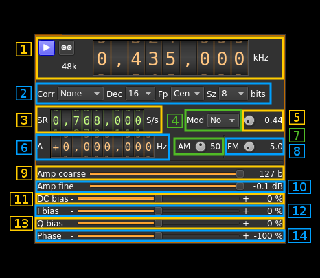
1: Common stream parameters
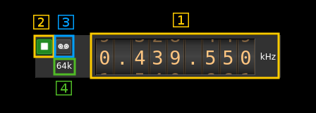
1.1: Frequency
This is the center frequency of reception in kHz.
1.2: Start/Stop
Device start / stop button.
- Blue triangle icon: device is ready and can be started
- Green square icon: device is running and can be stopped
- Magenta (or pink) square icon: an error occurred. In the case the device was accidentally disconnected you may click on the icon, plug back in and start again.
1.3: Record
Record baseband I/Q stream toggle button
1.4: Stream sample rate
Baseband I/Q sample rate in kS/s. This is the device to host sample rate (3) divided by the decimation factor (4).
2: Various options
2.1: Auto corrections
This combo box control the local DSP auto correction options:
- None: no correction
- DC: auto remove DC component
- DC+IQ: auto remove DC component and correct I/Q balance.
2.2: Decimation factor
The I/Q stream from the generator is downsampled by a power of two before being sent to the passband. Possible values are increasing powers of two: 1 (no decimation), 2, 4, 8, 16, 32. This exercises the decimation chain.
This exercises the decimation chain.
2.3: Baseband center frequency position relative the center frequency
- Cen: the decimation operation takes place around the center frequency Fs
- Inf: the decimation operation takes place around Fs - Fc.
- Sup: the decimation operation takes place around Fs + Fc.
With SR as the sample rate before decimation Fc is calculated as:
- if decimation n is 4 or lower: Fc = SR/2^(log2(n)-1). The device center frequency is on the side of the baseband. You need a RF filter bandwidth at least twice the baseband.
- if decimation n is 8 or higher: Fc = SR/n. The device center frequency is half the baseband away from the side of the baseband. You need a RF filter bandwidth at least 3 times the baseband.
2.4: Sample size
This is the sample size in number of bits. It corresponds to the actual sample size used by the devices supported:
- 8: RTL-SDR, HackRF
- 12: Airspy, BladeRF, LimeSDR, PlutoSDR, SDRplay
- 16: Airspy HF+, FCD Pro, FCD Pro+
3: Sample rate
This controls the generator sample rate in samples per second.
4: Modulation
- No: No modulation
- AM: Amplitude modulation (AM)
- FM: Frequency modulation (FM)
5: Modulating tone frequency
This controls the modulating tone frequency in kHz in 10 Hz steps.
6: Carrier shift from center frequency
Use this control to set the offset of the carrier from the center frequency of reception.
7: AM modulation factor
This controls the AM modulation factor from 0 to 99%
8: FM deviation
This controls the frequency modulation deviation in kHz in 100 Hz steps. It cannot exceed the sample rate.
9: Amplitude coarse control
This slider controls the number of amplitude bits by steps of 100 bits. The total number of amplitude bits appear on the right.
10: Amplitude fine control
This slider controls the number of amplitude bits by steps of 1 bit. The signal power in dB relative to the maximum power (full bit range) appear on the right.
11: DC bias
Use this slider to give a DC component in percentage of maximum amplitude.
12: I bias
Use this slider to give an in-phase (I) bias in percentage of maximum amplitude.
13: Q bias
Use this slider to give an quadrature-phase (Q) bias in percentage of maximum amplitude.
14: Phase imbalance
Use this slider to introduce a phase imbalance in percentage of full period (continuous wave) or percentage of I signal injected in Q (AM, FM).


