| .. | ||
| CMakeLists.txt | ||
| demodnfm.pro | ||
| nfmdemod.cpp | ||
| nfmdemod.h | ||
| nfmdemodgui.cpp | ||
| nfmdemodgui.h | ||
| nfmdemodgui.ui | ||
| nfmplugin.cpp | ||
| nfmplugin.h | ||
| readme.md | ||
NFM demodulator plugin
Introduction
This plugin can be used to listen to a narrowband FM modulated signal. "Narrowband" means that the bandwidth can vary from 5 to 40 kHz.
Interface
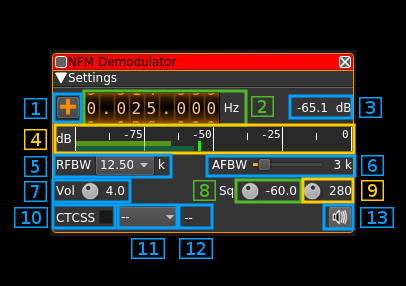
1: Frequency shift from center frequency of reception direction
The "+/-" button on the left side of the dial toggles between positive and negative shift.
2: Frequency shift from center frequency of reception value
Use the wheels to adjust the frequency shift in Hz from the center frequency of reception. Left click on a digit sets the cursor position at this digit. Right click on a digit sets all digits on the right to zero. This effectively floors value at the digit position.
3: Channel power
Average total power in dB relative to a +/- 1.0 amplitude signal received in the pass band.
4: Level meter in dB
- top bar (green): average value
- bottom bar (blue green): instantaneous peak value
- tip vertical bar (bright green): peak hold value
5: RF bandwidth
This is the bandwidth in kHz of the channel signal before demodulation. It can be set in steps as 5, 6.25, 8.33, 10, 12.5, 15, 20, 25 and 40 kHz.
6: AF bandwidth
This is the bandwidth of the audio signal in kHz (i.e. after demodulation). It can be set in continuous kHz steps from 1 to 20 kHz.
7: Volume
This is the volume of the audio signal from 0.0 (mute) to 10.0 (maximum). It can be varied continuously in 0.1 steps using the dial button.
8: Squelch threshold
This is the squelch threshold in dB. The average total power received in the signal bandwidth before demodulation is compared to this value and the squelch input is open above this value. It can be varied continuously in 0.1 dB steps from 0.0 to -100.0 dB using the dial button.
9: Squelch gate
This is the squelch gate in milliseconds. The squelch input must be open for this amount of time before the squelch actually opens. This prevents the opening of the squelch by parasitic transients. It can be varied continuously in 10ms steps from 10 to 500ms using the dial button.
10: CTCSS on/off
Use the checkbox to toggle CTCSS activation. When activated it will look for a tone squelch in the demodulated signal and display its frequency (see 10).
11: CTCSS tone
This is the tone squelch in Hz. It can be selected using the toolbox among the usual CTCSS values and -- for none. When a value is given and the CTCSS is activated the squelch will open only for signals with this tone squelch.
12: CTCSS tone value
This is the value of the tone squelch received when the CTCSS is activated. It displays -- if the CTCSS system is de-activated.
13: Audio mute
Use this button to toggle audio mute for this channel. The button will light up in green if the squelch is open. This helps identifying which channels are active in a multi-channel configuration.
