8.9 KiB
ATV demodulator plugin
Introduction
This plugin can be used to view amateur analog television transmissions a.k.a ATV. The transmitted video signal can be black and white or color (PAL, NTSC) but only the black and white levels (luminance) is retained and hence image is black and white. There is no provision to demodulate the audio subcarrier either. The modulation can be either AM or FM. A plugin supporting audio can be used in the same passband to demodulate an audio carrier but not a subcarrier which excludes FM.
The whole bandwidth available to the channel is used. That is it runs at the device sample rate possibly downsampled by a power of two in the source plugin. It expects an integer number of MS/s and standard image quality requires a sample rate of at least 4 MS/s. The Airspy Mini 3 MS/s mode may still be acceptable. Anything below should be considered experimental quality.
Interface
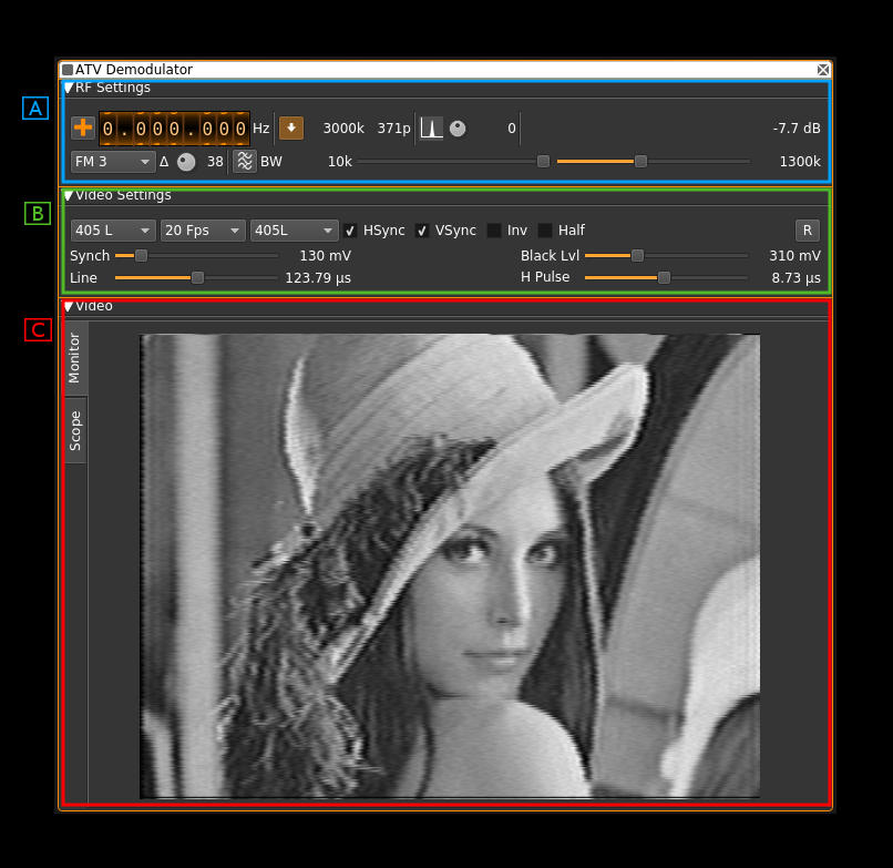
The interface is divided into three collapsable sections:
- A: the RF settings
- B: the video settings
- C: the video monitor and scope
Each part is detailed next
A: RF settings
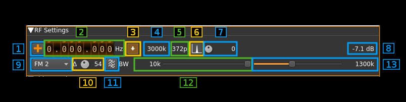
1: Frequency shift from center frequency of reception direction
The "+/-" button on the left side of the dial toggles between positive and negative shift.
2: Frequency shift from center frequency of reception value
Use the wheels to adjust the frequency shift in Hz from the center frequency of reception. Left click on a digit sets the cursor position at this digit. Right click on a digit sets all digits on the right to zero. This effectively floors value at the digit position.
3: Rational downsampler toggle
Use this toggle button to enable or disable the rational downsampler.
Without downsampling the sample rate given by the source plugin is directly applied to the channel.
When the downsampler is engaged the channel sample rate is the closest multiple of 0.5 MS/s below the source sample rate. e.g for a source sample rate of 3.2 MS/s this will be 3 MS/s. If a non null sample rate cannot be obtained the decimator is disabled and the source sample rate is used instead.
When the downsampler is engaged the signal is lowpass filtered and the cutoff frequency can be adjusted with the in band filter cutoff slider (13). This works also when the decimation ratio is 1.0 e.g source sample rate is 3 MS/s.
4: Channel sample rate
This is the channel sample rate in kS/s possibly downsampled from source when rational downsampler is engaged (3).
5: Number of points (or samples) per line
This is the number of points or samples per complete line including sync and black porchs.
6: BFO PLL lock indicator
Warning: this is experimental.
When single sideband demodulation is selected (USB, LSB) the BFO is phased locked to the carrier. This indicator turns green if the PLL is locked.
7: BFO frequency adjustment
Warning: this is experimental.
This allows adjstment of BFO frequency in 10 Hz steps from -5 to +5 kHz. You will have to look for the right value to lock to the carrier. See (6) for the lock indicator.
The BFO base frequency in Hz appears on the right. Actual frequency may change acoording to PLL locking to the carrier.
8: Channel power
Average total power in dB relative to a ±1.0 amplitude signal generated in the pass band.
9: Modulation
- FM1: this is Frequency Modulation with approximative demodulation algorithm not using atan2
- FM2: this is Frequency Modulation with less approximative demodulation algorithm still not using atan2
- FM3: this is Frequency Modulation with atan2 approximation
- AM: this is Amplitude Modulation
- USB: USB demodulation synchronous to the carrier
- LSB: USB demodulation synchronous to the carrier
For FM choose the algorithm that best suits your conditions.
USB and LSB modes are experimental and do not show good results for present standards sample rates.
10: FM excursion adjustment
Using this button you can adjust the nominal FM excursion as a percentage of the channel bandwidth that is displayed on the right of the button. When a signal with this excursion is received the demodulated signal is in the range -0.5/+0.5 which is shifted to a 0/1 range video signal.
Note that the value is accurate only with the atan2 differential demodulator i.e. FM3. With FM1 and FM2 you will have to adjust it for best image results. You can use the scope as an aid to try to fit the video signal in the 0/1 range.
11: FFT asymmetrical filter toggle
Use this button to enable/disable the FFT asymmetrical filter.
12: FFT asymmetrical filter opposite band cutoff frequency
For all modulations except LSB this is the lower side band.
This slider lets you adjust the opposite band cutoff frequency of the FFT asymmetrical filter. The value in MHz appears on the left of the slider.
13: FFT asymmetrical filter in band cutoff frequency
For all modulations except LSB this is the upper side band.
This slider lets you adjust the in band cutoff frequency of the FFT asymmetrical filter. The value in MHz appears on the left of the slider.
If the rational downsampler is engaged (3) and the FFT filter is not engaged (11) this slider controls the downsampler cutoff frequency.
B: Video settings
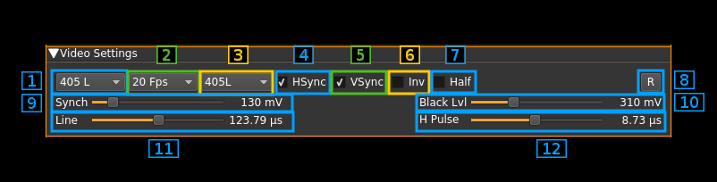
1: Nominal number of lines
This is the total number of lines including all possible synchronization signals.
Choice is between 625, 525 and 405 lines. The number of image lines depends on the synchronization scheme.
2: Frames Per Second
This combo lets you chose between a 30, 25, 20 and 16 FPS. This is the resulting FPS. In interleaved modes the half frame rate is doubled.
3: Synchronization standard
This combo lets you set the standard type relating essentially to frame synchronization. Choice is between:
- PAL625L: this is based on the classical 625 lines PAL system. It uses 7 or 8 synchronization lines depending on the half frame (field). It has also 17 black lines on the top of each half frame.
- PAL525L: the only difference with PAL625L is the number of black lines which is down to 15
- 405L: this is not the British standard. It just follows the same sheme as the two above but with only 7 black lines per half frame
4: Horizontal sync
Check/uncheck this box to toggle horizontal synchronization processing.
5: Vertical sync
Check/uncheck this box to toggle vertical synchronization processing.
6: Invert video
Check/uncheck this box to toggle video signal inversion. This does not work well in AM for now.
7: Half frames
Check this box to render only half of the frames for slow processors.
8: Reset defaults
Use this push button to reset values to a standard setting:
- FM1 modulation
- 625 lines
- 25 FPS
- PAL 625L standard
- Horizontal and vertical syncs active
- No video inversion
- Interlacing
- 100 mV sync level
- 310 mV black level
- 64 microsecond line length
- 4.7 microsecond sync pulse length
9: Synchronization level
Use this slider to adjust the top level of the synchronization pulse on a 0 to 1V scale. The value in mV appears on the right of the slider. Nominal value: 100 mV.
10: Black level
Use this slider to adjust the black level of the video signal on a 0 to 1V scale. The value in mV appears on the right of the slider. Nominal value: 310 mV.
11: Line length
This is the line length in time units. The value in microseconds appears on the right of the slider. Nominal value: 64 microseconds.
12: Horizontl synchronization pulse length
This is the length in time units of a synchronization top. The value in microseconds appears on the right of the slider. Nominal value 3 microseconds.
C: Image
Monitor
Select monitor with the monitor tab on the left side.
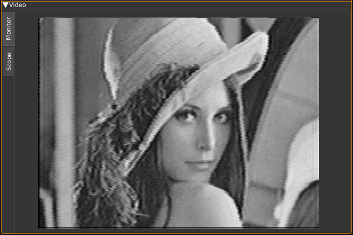
This is where the TV image appears. Yes on the screenshot this is the famous Lenna. The original image is 512 × 512 pixels so it has been cropped to fit the 4:3 format. The screen geometry ratio is fixed to 4:3 format.
Scope
Select scope with the scope tab on the left side.

This is a scope widget fed with the video signal. Controls of the scope are the same as with the ChannelAnalyzerNG plugin. Please refer to the readme of this plugin for more details.
Note that the video signal is a real signal so the imaginary part is always null. In fact only the "Real" mode for the trace and trigger is interesting.