7.3 KiB
BladeRF 2.0 micro (v2) input plugin
Introduction
This input sample source plugin gets its samples from a BladeRF 2.0 micro device using LibbladeRF v.2.
Build
The plugin will be built only if the BladeRF host library is installed in your system. If you build it from source and install it in a custom location say: /opt/install/libbladeRF you will have to add -DBLADERF_INCLUDE_DIR=/opt/install/libbladeRF to the cmake command line.
Note that libbladeRF v2 with git tag 2018.08 should be used (official release). The FPGA image v0.7.3 should be used accordingly. The FPGA .rbf file should be copied to the folder where the sdrangel binary resides. You can download FPGA images from here
The BladeRF Host library is also provided by many Linux distributions (check its version) and is built in the SDRangel binary releases.
Interface
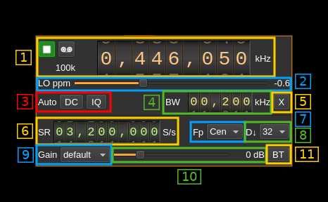
1: Common stream parameters
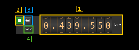
1.1: Frequency
This is the center frequency of reception in kHz. The center frequency is the same for all Rx channels. The GUI of the sibling channel if present is adjusted automatically.
1.2: Start/Stop
Device start / stop button.
- Blue triangle icon: device is ready and can be started
- Green square icon: device is running and can be stopped
- Magenta (or pink) square icon: an error occurred. In the case the device was accidentally disconnected you may click on the icon, plug back in and start again.
1.3: Record
Record baseband I/Q stream toggle button
1.4: Stream sample rate
Baseband I/Q sample rate in kS/s. This is the device sample rate (4) divided by the decimation factor (6).
2: LO ppm correction
Use this slider to adjust LO correction in ppm. It can be varied from -20.0 to 20.0 in 0.1 steps and is applied in software. This applies to the oscillator that controls both the Rx and Tx frequency therefore it is also changed on the related Rx and Tx plugin(s) if they are active.
3: Auto correction options
These buttons control the local DSP auto correction options:
- DC: auto remove DC component
- IQ: auto make I/Q balance. The DC correction must be enabled for this to be effective.
4: Rx filter bandwidth
This is the Rx filter bandwidth in kHz. Minimum and maximum values are adjusted automatically. Normal range is from 200 kHz to 56 MHz. The Rx filter bandwidth is the same for all Rx channels. The GUI of the sibling channel if present is adjusted automatically.
5: Transverter mode open dialog
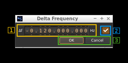
This button opens a dialog to set the transverter mode frequency translation options:
Note that if you mouse over the button a tooltip appears that displays the translating frequency and if translation is enabled or disabled. When the frequency translation is enabled the button is lit.
5.1: Translating frequency
You can set the translating frequency in Hz with this dial. Use the wheels to adjust the sample rate. Left click on a digit sets the cursor position at this digit. Right click on a digit sets all digits on the right to zero. This effectively floors value at the digit position. Wheels are moved with the mousewheel while pointing at the wheel or by selecting the wheel with the left mouse click and using the keyboard arrows. Pressing shift simultaneously moves digit by 5 and pressing control moves it by 2.
The frequency set in the device is the frequency on the main dial (1) minus this frequency. Thus it is positive for down converters and negative for up converters.
For example a mixer at 120 MHz for HF operation you would set the value to -120,000,000 Hz so that if the main dial frequency is set at 7,130 kHz the PlutoSDR will be set to 127.130 MHz.
If you use a down converter to receive the 6 cm band narrowband center frequency of 5670 MHz at 432 MHz you would set the translating frequency to 5760 - 432 = 5328 MHz thus dial +5,328,000,000 Hz.
For bands even higher in the frequency spectrum the GHz digits are not really significant so you can have them set at 1 GHz. Thus to receive the 10368 MHz frequency at 432 MHz you would set the translating frequency to 1368 - 432 = 936 MHz. Note that in this case the frequency of the LO used in the mixer of the transverter is set at 9936 MHz.
The Hz precision allows a fine tuning of the transverter LO offset
5.2: Translating frequency enable/disable
Use this toggle button to activate or deactivate the frequency translation
5.3: Confirmation buttons
Use these buttons to confirm ("OK") or dismiss ("Cancel") your changes.
6: Device sample rate
This is the BladeRF device ADC sample rate in S/s.
Use the wheels to adjust the sample rate. Left click on a digit sets the cursor position at this digit. Right click on a digit sets all digits on the right to zero. This effectively floors value at the digit position. Wheels are moved with the mousewheel while pointing at the wheel or by selecting the wheel with the left mouse click and using the keyboard arrows. Pressing shift simultaneously moves digit by 5 and pressing control moves it by 2.
The ADC sample rate is the same for all Rx channels. The GUI of the sibling channel if present is adjusted automatically.
7: Baseband center frequency position relative the the BladeRF Rx center frequency
Possible values are:
- Cen: the decimation operation takes place around the BladeRF Rx center frequency Fs
- Inf: the decimation operation takes place around Fs - Fc.
- Sup: the decimation operation takes place around Fs + Fc.
With SR as the sample rate before decimation Fc is calculated as:
- if decimation n is 4 or lower: Fc = SR/2^(log2(n)-1). The device center frequency is on the side of the baseband. You need a RF filter bandwidth at least twice the baseband.
- if decimation n is 8 or higher: Fc = SR/n. The device center frequency is half the baseband away from the side of the baseband. You need a RF filter bandwidth at least 3 times the baseband.
8: Decimation factor
The I/Q stream from the BladeRF ADC is downsampled by a power of two before being sent to the passband. Possible values are increasing powers of two: 1 (no decimation), 2, 4, 8, 16, 32, 64.
9: Gain mode
This selects the gain processing in use. Values are fetched automatically from the device. Normal values are
- default: AGC with default behavior
- Manual: Manual. Use control (9) to adjust gain
- fast: fast AGC
- slow: slow AGC
- hybrid: hybrid AGC
10: Manual gain control
Use this slider to adjust gain in manual mode. This control is disabled in non manual modes (all modes but manual). The minumum, maximum and step values are fetched automatically from the device and may vary depending on the center frequency. For frequencies around 400 MHz the gain varies from -16 to 60 dB in 1 dB steps.
11: Bias tee control
Use this toggle button to activate or de-activate the bias tee. Note that according to BladeRF v2 specs the bias tee is simultanously present on all Rx RF ports. The GUI of the sibling channel if present is adjusted automatically.


