6.1 KiB
LimeSDR output plugin
Introduction
This output sample sink plugin sends its samples to a LimeSDR device. LimeSDR plugins are not included in the Win32 binary distribution.
⚠ LimeSuite library is difficult to implement due to the lack of documentation. The plugins should work normally when running as single instances. Support of both Rx and/or both Rx running concurrently is experimental.
LimeSDR is a 2x2 MIMO device so it has two transmitting channels that can run concurrently. To activate the second channel when the first is already active just open a new sink tab in the main window (Devices -> Add sink device) and select the same LimeSDR device.
Build
The plugin will be built only if LimeSuite is installed in your system. To build and install LimeSuite from source do:
sudo apt-get install libsqlite3-devgit clone https://github.com/myriadrf/LimeSuite.gitcd LimeSuitemkdir builddircd builddircmake -DCMAKE_INSTALL_PREFIX=/opt/install/LimeSuitemake -j8make install
Then add the following defines on cmake command line:
-DLIMESUITE_INCLUDE_DIR=/opt/install/LimeSuite/include -DLIMESUITE_LIBRARY=/opt/install/LimeSuite/lib/libLimeSuite.so
Installation from binary packages
☞ LimeSuite is built in the binary packages so there is no external dependency
Interface
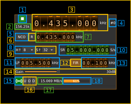
1: Start/Stop
Device start / stop button.
- Blue triangle icon: device is ready and can be started
- Green square icon: device is running and can be stopped
- Magenta (or pink) square icon: an error occured. In the case the device was accidentally disconnected you may click on the icon to stop, plug back in, check the source on the sampling devices control panel and start again.
2: Baseband sample rate
This is the baseband sample rate in kS/s before interpolation (9) to produce the final stream that is sent to the LimeSDR device. Thus this is the device sample rate (10) divided by the interpolation factor (9).
3: Frequency
This is the center frequency of transmission in kHz.
4: Channel number
LimeSDR is a 2x2 MIMO device so it has two transmitting channels. This shows the corresponding Tx channel index (0 or 1).
5: NCO toggle
The button is lit when NCO is active and dark when inactive.
Use this button to activate/deactivate the TSP NCO. The LMS7002M chip has an independent NCO in each Tx channel that can span the bandwidth sent to the DAC. This effectively allows non zero digital IF.
6: Zero (reset) NCO frequency
Use this push button to reset the NCO frequency to 0 and thus center on the main passband of the DAC.
7: Center frequency with NCO engaged
This is the center frequency of the mix of LO and NCO combined and is the sink passband center frequency when the NCO is engaged. Use the thumbwheels to adjust frequency as done with the LO (1.1). The boundaries are dynamically calculated from the LO center frequency and sample rate.
8: LMS7002M hardware interpolation factor
The TSP block in the LMS7002M hardware has an interpolation chain that acts on both Tx channels. It is composed of 5 halfband interpolation stages and therefore can achieve interpolation between 1 (no interpolation) and 32 in increasing powers of 2: 1, 2, 4, 8, 16, 32.
Thus the actual sample rate of the DAC is the stream sample rate (10) multiplied by this factor. In the screenshot example this yields a 40 MS/s rate at the DAC.
9: Software interpolation factor
The I/Q stream from the baseband is upsampled by a power of two by software inside the plugin before being sent to the LimeSDR device. Possible values are increasing powers of two: 1 (no interpolation), 2, 4, 8, 16, 32.
10: Device stream sample rate
This is the LMS7002M device to/from host stream sample rate in S/s.
Use the wheels to adjust the sample rate. Left click on a digit sets the cursor position at this digit. Right click on a digit sets all digits on the right to zero. This effectively floors value at the digit position.
The LMS7002M uses the same clock for both the ADCs and DACs therefore this sample rate affects all of the 2x2 MIMO channels.
11: Tx hardware filter bandwidth
This is the Tx hardware filter bandwidth in kHz in the LMS7002M device for the given channel. Boundaries are updated automatically but generally are from 5 to 130 MHz in 1 kHz steps. Use the wheels to adjust the value.
12: TSP FIR filter toggle
The TSP in the LMS7002M chip has a FIR filter chain per channel. Use this button to activate or deactivate the TSP FIR filter.
13: TSP FIR filter bandwidth
Use the wheels to adjust the bandwidth of the hardware TSP FIR filter.
14: Gain
Use this slider to adjust the global gain of the Tx chain. LimeSuite software automatically set optimal values of the amplifiers to achive this global gain. This gain can be set between 0 and 70 dB in 1 dB steps. The value in dB appears at the right of the slider.
15: Stream status indicator
This label turns green when status can be obtained from the current stream. Usually this means that the stream is up and running but not necessarily streaming data. The various status elements appear next on the same line (16, 17, 18)
16: Stream warning indicators
- U: turns red if stream experiences underruns
- O: turns red if stream experiences overruns
- P: turns red if stream experiences packet drop outs
17: Stream global (all Tx) throughput in MB/s
This is the stream throughput in MB/s and is usually about 3 times the sample rate for a single stream and 6 times for a dual Tx stream. This is due to the fact that 12 bits samples are used and although they are represented as 16 bit values only 12 bita travel on the USB link.
⚠ it has been found that in practice to get a clean output the gain should not exceed ~4dB with standard levels in the channel plugins.
18: FIFO status
This is the fill percentage of the Tx FIFO in the LimeSuite interface. In normal conditions this should be ~100%.
