4.2 KiB
BladeRF input plugin
Introduction
This input sample source plugin gets its samples from a BladeRF device.
Build
The plugin will be built only if the BladeRF host library is installed in your system. If you build it from source and install it in a custom location say: /opt/install/libbladeRF you will have to add -DLIBBLADERF_INCLUDE_DIR=/opt/install/libbladeRF/include -DLIBBLADERF_LIBRARIES=/opt/install/libbladeRF/lib/libbladeRF.so to the cmake command line.
The BladeRF Host library is also provided by many Linux distributions and is built in the SDRangel binary releases.
Interface
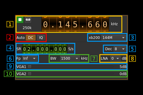
1: Common stream parameters
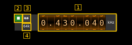
1.1: Frequency
This is the center frequency of reception in kHz.
1.2: Start/Stop
Device start / stop button.
- Blue triangle icon: device is ready and can be started
- Green square icon: device is running and can be stopped
- Magenta (or pink) square icon: an error occured. In the case the device was accidentally disconnected you may click on the icon, plug back in and start again.
1.3: Record
Record baseband I/Q stream toggle button
1.4: Stream sample rate
Baseband I/Q sample rate in kS/s. This is the device sample rate (4) divided by the decimation factor (6).
2: Auto correction options
These buttons control the local DSP auto correction options:
- DC: auto remove DC component
- IQ: auto make I/Q balance
3: XB-200 add-on control
This controls the optional XB-200 add-on when it is fitted to the BladeRF main board. These controls have no effect if the XB-200 board is absent. Options are:
- None: XB-200 is ignored
- Bypass: XB-200 is passed through
- Auto 1dB: The 50, 144 and 220 MHz filters are switched on automatically according to the frequency of reception when it is within the -1 dB passband of the filters
- Auto 3dB: The 50, 144 and 220 MHz filters are switched on automatically according to the frequency of reception when it is within the -3 dB passband of the filters
- Custom: The signal is routed through a custom filter
- 50M: The signal is routed through the 50 MHz filter
- 144M: The signal is routed through the 144 MHz filter
- 222M: The signal is routed through the 222 MHz filter
4: Device sample rate
This is the BladeRF device ADC sample rate in S/s.
Use the wheels to adjust the sample rate. Left click on a digit sets the cursor position at this digit. Right click on a digit sets all digits on the right to zero. This effectively floors value at the digit position.
5: Decimation factor
The I/Q stream from the BladeRF ADC is doensampled by a power of two before being sent to the passband. Possible values are increasing powers of two: 1 (no decimation), 2, 4, 8, 16, 32.
6: Baseband center frequency position relative the the BladeRF Rx center frequency
Possible values are:
- Cen: the decimation operation takes place around the BladeRF Rx center frequency
- Inf: the decimation operation takes place around the center of the lower half of the BladeRF Rx passband.
- Sup: the decimation operation takes place around the center of the upper half of the BladeRF Rx passband.
7: Rx filter bandwidth
This is the Rx filter bandwidth in kHz in the LMS6002D device. Possible values are: 1500, 1750, 2500, 2750, 3000, 3840, 5000, 5500, 6000, 7000, 8750, 10000, 12000, 14000, 20000, 28000 kHz.
8: LNA gain
This is the LNA gain in dB. LNA is inside the LMS6002D chip and is placed before the RF mixer. Possible values are:
- 0dB: no gain
- 3dB
- 6dB
9: Variable gain amplifier #1 gain
The VGA1 gain can be adjusted from 5 dB to 30 dB in 1 dB steps. The VGA1 is inside the LMS6002D chip and is placed between the RF mixer and the baseband filter.
10: Variable gain amplifier #2 gain
The VGA2 gain can be adjusted from 0 dB to 30 dB in 3 dB steps. The VGA2 is inside the LMS6002D chip and is placed between the baseband filter and the ADC.

