4.6 KiB
AM demodulator plugin
Introduction
This plugin can be used to listen to a narrowband amplitude modulated signal. "Narrowband" means that the bandwidth can vary from 1 to 40 kHz.
Interface
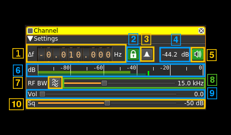
The top and bottom bars of the channel window are described here
Channel frequency entry mode
Select from one of the following modes to determine how the channel center frequency is calculated:
- Δf - Specify an offset in Hz from device center frequency.
- MW - Specify a LW/MW absolute frequency in kHz. Right click to snap channel marker to nearest 1kHz when dragged.
- 25k - Specify absolute frequency in MHz. Right click to snap channel marker to 25kHz channels when dragged.
- 8.33k - Specify airband 8.33kHz channel number. Right click to snap channel marker to 8.33kHz channels when dragged.
1: Channel Frequency
Specifies channel center frequency according to frequency entry mode:
- Δf - Offset in Hz from device center frequency;
- MW - Absolute frequency in kHz.
- 25k - Absolute frequency in MHz.
- 8.33k - Airband 8.33kHz channel number.
Use the wheels to adjust the value. Left click on a digit sets the cursor position at this digit. Right click on a digit sets all digits on the right to zero. This effectively floors value at the digit position. Wheels are moved with the mousewheel while pointing at the wheel or by selecting the wheel with the left mouse click and using the keyboard arrows. Pressing shift simultaneously moves digit by 5 and pressing control moves it by 2.
2: PLL and synchronous AM
Use this toggle button to turn on or off the PLL locking and synchronous AM detection. When on the input signal is mixed with the NCO of the PLL that locks to the carrier of the AM transmission. Then the signal is processed as a DSB or SSB (see control 3) modulated signal. The main advantage compared to envelope detection is a better resilience to carrier selective fading. This does not prevents all selective fading distortion but addresses the most annoying.
When the PLL is locked the icon lights up in green. The frequency shift from carrier appears in the tooltip. Locking indicator is pretty sharp with about +/- 100 Hz range.
3: DSB/SSB selection
Use the left mouse button to toggle DSB/SSB operation. Sometimes one of the two sidebands is affected by interference. Selecting SSB may help by using only the sideband without interference. Right click to open a dialog to select which sideband is used (LSB or USB).
4: Channel power
Average total power in dB relative to a +/- 1.0 amplitude signal received in the pass band.
5: Audio mute and audio output select
Left click on this button to toggle audio mute for this channel. The button will light up in green if the squelch is open. This helps identifying which channels are active in a multi-channel configuration.
If you right click on it, it will open a dialog to select the audio output device. See audio management documentation for details.
6: Level meter in dB
- top bar (green): average value
- bottom bar (blue green): instantaneous peak value
- tip vertical bar (bright green): peak hold value
7:Bandpass boxcar filter toggle
Use this button to enable or disable the bandpass boxcar (sharp) filter with low cutoff at 300 Hz and high cutoff at half the RF bandwidth. This may help readability of low signals on air traffic communications but degrades audio on comfortable AM broadcast transmissions.
8: RF bandwidth
This is the bandwidth in kHz of the channel signal before demodulation. It can be set continuously in 1 kHz steps from 1 to 40 kHz.
9: Volume
This is the volume of the audio signal from 0.0 (mute) to 10.0 (maximum). It can be varied continuously in 0.1 steps using the dial button.
10: Squelch threshold
This is the squelch threshold in dB. The average total power received in the signal bandwidth before demodulation is compared to this value and the squelch input is open above this value. It can be varied continuously in 0.1 dB steps from 0.0 to -100.0 dB using the dial button.
11: Audio bandwidth
Specifies cutoff frequency of low pass (or band pass if boxcar (7) enabled) filter applied to audio. In many use cases, this can be the same as the RF bandwidth (8). However, where offset carrier is used (a.k.a CLIMAX as used by some ATC ground stations), this can reduce noise, when the RF bandwidth is set around ~20kHz to cope with the offset, but the audio is only ~5-6kHz wide.
